
|
Features
EuroSim Scheduling
Creating a Schedule
To make a schedule, there are two main steps involved:
-
entrypoints from the source code are collected together
into groups: tasks; within each task, the list of API
entrypoints is executed sequentially;
-
execution of tasks wrt one another and synchronisation
points, ie. the overal execution schedule, is specified
using a graphical Schedule Editor.
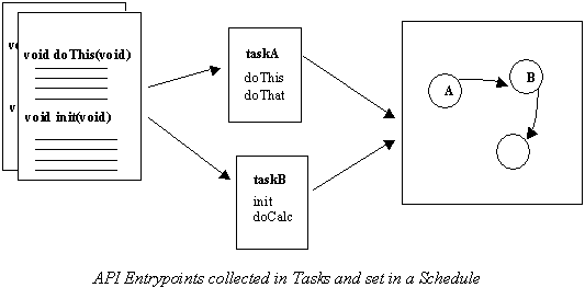
Tasks
A task is a list of API entrypoints to be executed
sequentially. The organisation of entrypoints into tasks is
an important activity, in order to take advantage of the
multi-processor environment.
A good selection optimises the potential for parallel
execution of the model. Dependencies between tasks, such as
data output/input, are expressed when building up the
schedule.
As an aid to scheduling, estimates for the duration of each
task execution can be provided. These are then analysed
during the schedule editing session to check for unfeasible
schedules.
Other attributes which can be provided per task include processor allocation, preemptability and priority.
Schedule
The schedule is divided into four sections, each
representing one of the four simulation states:
initialising, executing, standby and exit. This means that
tasks can be triggered for execution in one or more of these
states or the transition between the states.
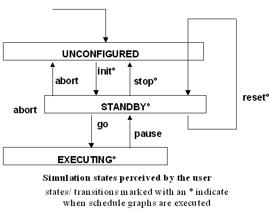
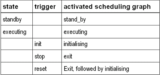
The specification of the schedule is done by using a
graphical editor, where the following components are
available for use in addition to graphical representations
of the tasks:
-
timer: generates triggers for task execution at a
specified frequency; offsets can be introduced to offset
pulses from this timer from those from other timers;
-
flow: allows completion of one task to be the signal to
trigger another directly;
-
input connector: a signal coming from the non real-time
domain which triggers a task; predefined input connnectors
include simulator state change events (eg.-for each of the
four scheduler states: STATE_ENTRY, STATE_EXIT) and
real-time errors; user-defined input connectors can also be
raised via mission action (MDL) scripts at runtime;
-
output connector: a flag raised by a completed task, which
can be recognised and acted on in the non real-time domain;
predefined output connectors include requests for state
changes (eg. ABORT) and scheduler mode switches (rt/nrt);
user-defined output connectors are also possible, and if
given the name of a task, will cause that task to run
outside the hard real-time domain (useful for eg. file
input/output tasks);
-
mutex: specifies that tasks reading/writing to this
'store' are mutually exclusive ie. should never be
executed simultaneously;
-
divider: decouples two (or more) dependent tasks which are
executing at different frequencies; transforms input/output
frequency eg. one writes at 100 Hz, the other reads at 10
Hz.
Execution of a Schedule
Examples are used to show how the scheduler handles the
activation of user tasks according to mutices, dividers,
dependencies, time requirements, and how the scheduler
handles state transitions between different simulation
states.
Dependencies, Mutices and Dividers
Dependencies, mutices and dividers are used to define a
sequence of tasks. Consider the following schedule:
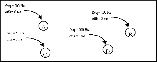
With this schedule it is defined that task A and D must be
activated each 5 ms, task B must be activated each 10 ms,
and task C must be activated each 20 ms. The maximum
frequency on which the scheduler can activate tasks is 200
Hz (default) for each of the simulation states. This means
that the 'real-time' is split up in time slots of 5 ms.
For the example as shown in the following diagram, the
scheduler will activate tasks A and D in slot 1,2,3,...,
task B in slot 2,4,6,..., and task C in slot 4,8,12,...

In the current example, the sequence of tasks within a
particular slot is not defined. To define the sequence
between tasks within the slots, dependencies (between tasks
with the same frequency) and dividers (for tasks with
different frequencies) should be used. In the next example,
the sequence of tasks within the timeslots is defined using
dependencies and two dividers.

Note that the frequency of task D is still 200Hz, the
frequency of task B is still 100Hz and that of task C still
50Hz. These frequencies are now defined in the output
frequency of the divider. With the dividers pictured above,
the timeslots and sequences of tasks within the slots, will
now become:

In the previous example, dividers were used to define the
sequences of tasks. With such a defined linear sequence, it
is implicit that tasks do not run simultaneously. An
alternative way to ensure that tasks are not executing
simultaneously but without explicitly defining a sequence is
to use mutices.
Tasks that read or write from the same mutex will never be
executed by the scheduler simultaneously. Consider a
schedule which is to contain a 'printing' task that prints
the contents of a linked list at 50 Hz, and an 'updating'
task that changes the contents of the list at 200 Hz. It is
obvious that the updating task may not run simultaneously
with the printing task. Use of a mutex between the two tasks
solves this problem.

State Transitions
A state transition can only occur at a main cycle
boundary. A main cycle has a period equal to the least
common multiple (LCM) of the periodic tasks computed over
all states of the simulator in the schedule. In the current
implementation, the main cycle is taken as the LCM of the
periods of all periodic tasks (over all states), instead of
the LCM of the periods of active tasks in the current
running state. This, for reasons of simplicity, is still
correct, although it may make the main cycle somewhat larger
than strictly necessary.
In the previous example there was a main cycle 'AD:ADB:AD:ADBC'
of 20 ms duration. This means that state transitions can only occur at each '4 slots'
boundary. For this reason the scheduler will delay the user's state transition request
until the end of slot 4, 8, 12, ... etc.
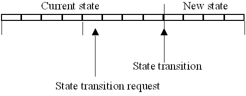
If in the period between the request and the transition more
state requests are given, these requests are buffered by the
scheduler (up to 32) and applied on a FIFO basis at the next
main cycle boundaries, with one being executed at a time.
Offsets
Offsets are used to 'delay' tasks to following time
slots. Consider the following schedule:

The 10 ms offset of task B will delay all activations of task B by two slots:

When offsets are used, state transitions will still be on
the main cycle boundaries. This means that task B must still
be activated (according to the current excuting schedule),
in the first two slots of the new state. This guarantees
that the number of activations for each tasks are always the
same, ie. a functional model will always complete leaving
the system in a deterministic state.

Note that no synchronisation whatsoever is performed between
the schedules in the 'old' and 'new' state: this is omitted
under the assumption that there is only one nontrivial
EuroSim state (state Executing), and that any other state is
to perform simple procedures, such as initialisation or
keeping hardware alive. Supporting state synchronisation
would unnecessarily add to the complexity of the
scheduler. The user must however be aware of a possible
overlap in execution of the schedules of two states 'just
after' a state transition when offsets are used.
An exception to the state transitions occurring at fixed
points is made for the transition to Unconfigured which is
triggered by an Abort request. An abort transition does not
wait until the main cycle boundary, but is directly done by
the scheduler. This means that all tasks, including tasks
with an offset, are directly stopped.
Extremely large offsets (offsets larger than the main cycle)
will increase the overlap period between two states. When
offsets larger than the main cycle are used; and new state
transitions are requested by the user during the overlap
period, the request will be delayed until the first main
cycle boundary after the overlapping period.


|

